
In the first step we said that thrust is the force that overcomes drag. In this step we take a close look at the part that produces thrust on propeller aircraft: the propeller.
A propeller is a rotating wing
The cross-section of each propeller blade is similar to a wing's airfoil. When the propeller turns, each blade turns the air just like a wing; but this time the force points not up but forward. NASA also describes a propeller as "a rotating wing".
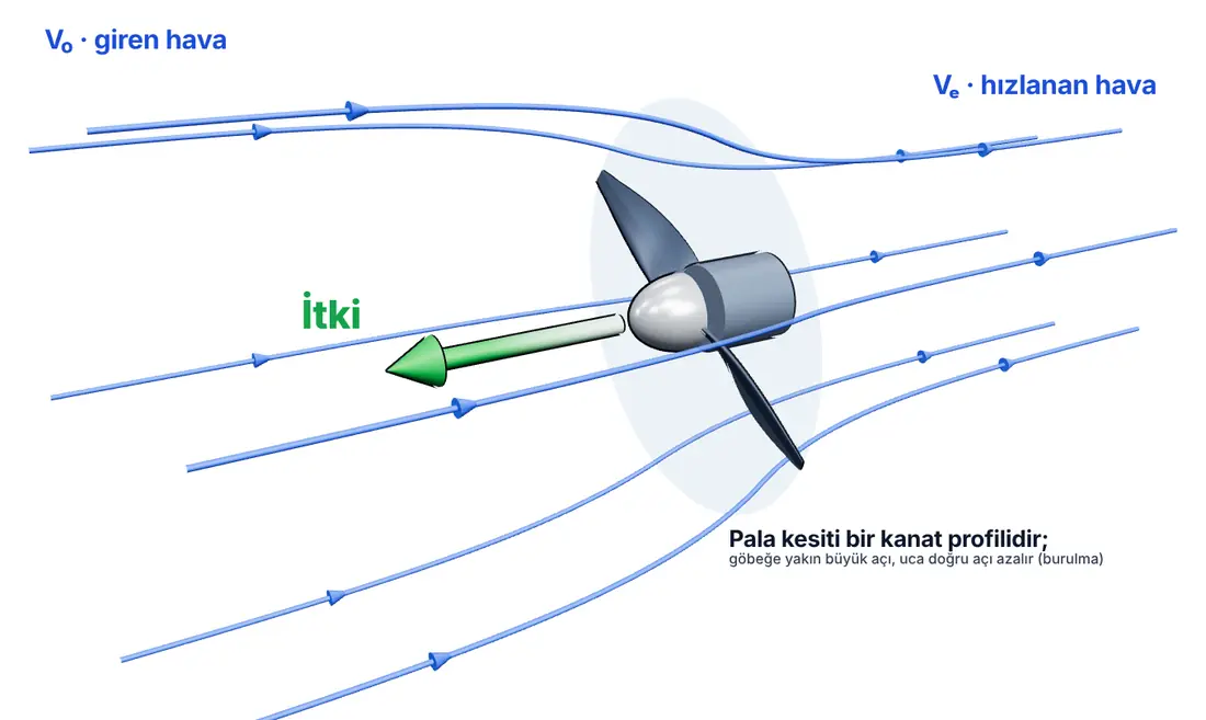
Why is the blade twisted?
The tip of the propeller moves much faster than the part near the hub. When a 10-inch (about 25 cm) propeller turns at 8,000 revolutions per minute, the blade tip moves at about 106 metres per second, while the regions near the hub move much more slowly. So that each section meets the air at a suitable angle, the blade is twisted from the hub to the tip: the angle is large near the hub and smaller towards the tip.
Where does thrust come from?
The propeller accelerates the air passing through it backwards. According to Newton's third law, the air pushes the propeller forward. In NASA's simplified model, thrust is calculated as:
Thrust = ρ · A · Vₚ · (Vₑ − V₀)
- ρ: air density
- A: propeller disc area
- Vₚ: speed of the air passing through the propeller plane (in the ideal model, the average of the inlet and outlet speeds)
- Vₑ − V₀: the speed gained by the air
This ideal calculation does not include losses, but it shows the logic: accelerating more air through a bigger disc means more thrust.
Diameter and pitch: what does "10x6" mean?
Model airplane propellers are usually named with two numbers. For example, a 10x6 propeller:
- 10: Propeller diameter, in inches (about 25.4 cm).
- 6: Pitch, in inches. A geometric value showing how far the propeller would move forward in one full turn if there were no slip.
The general trends are:
- Larger diameter: Moves more air; gives stronger pull at low speeds.
- Larger pitch: Pushes the air more on each turn; suits higher flying speeds, but can be less effective for take-off and climbing.
- Increasing both asks more power from the motor. The motor draws more current, and the motor, ESC and battery heat up.
Side effects of the propeller
The FAA's handbook explains certain left-turning tendencies caused by the propeller on single-engine propeller airplanes (for propellers turning clockwise as seen from the pilot's seat): engine torque, the spiralling slipstream hitting the fuselage, P-factor and gyroscopic effect. On model airplanes, the tendency of the airplane to pull to one side on take-off also comes from these effects. That is why it is important to open the throttle slowly on take-off and correct with the rudder.
Safety: a propeller is a blade
- Remove the propeller while working on the model, adjusting it or testing the controls.
- Before connecting the battery, make sure the throttle stick on the transmitter is all the way down.
- Do not stand in the plane of the propeller while the motor is running; a broken blade is thrown out in this plane.
- Do not use cracked, nicked or propellers that have hit the ground; an unbalanced propeller causes vibration and can break.
Try it yourself
Enter your propeller's diameter, pitch and rpm. See on the chart why, at the same power, a larger-diameter propeller produces more static thrust.
JavaScript must be enabled in your browser for this interactive tool.
We have completed the first part of the series
In eight steps we have covered the four forces, how lift is produced, the lift equation, the stall, the control surfaces, the centre of gravity, the atmosphere and the propeller. In the next steps we will move on to aircraft performance and to how you can use this knowledge when choosing your first model airplane.
Sources
- NASA Glenn Research Center. Propeller Thrust
- Federal Aviation Administration (FAA). Pilot's Handbook of Aeronautical Knowledge (FAA-H-8083-25C). Chapter 7: Aircraft Systems (propellers); Chapter 5: Aerodynamics of Flight (left-turning tendencies)
- NASA Glenn Research Center. Four Forces on an Airplane
This article was written by SVR AEROTECH as original work, drawing on the sources above; the figures belong to SVR AEROTECH. Quoted information belongs to the respective source owners.