
So far we have seen the forces that keep the airplane in the air and the limits of the wing. In this step we move on to how the pilot controls the airplane. A car only turns left and right; an airplane moves in three dimensions.
The three axes
In the air an airplane rotates around three imaginary axes. All three axes meet at the airplane's centre of gravity. When the control surfaces move, the force they produce rotates the airplane around this point.
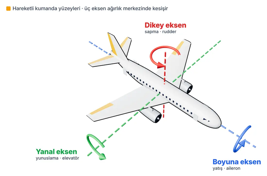
- Longitudinal axis: Runs from the nose to the tail. Motion around this axis is called roll.
- Lateral axis: Runs from one wingtip to the other. Motion around this axis is called pitch; the nose goes up or down.
- Vertical axis: Passes through the airplane from top to bottom. Motion around this axis is called yaw; the nose turns left or right.
Aileron: the roll control
The ailerons are the movable surfaces on the outer rear part of the wings, and they move in opposite directions. To roll right, the right aileron goes up and the left aileron goes down.
The aileron that goes down increases the lift of its wing; the aileron that goes up reduces the lift of its own wing, the opposite wing. This difference in lift between the two wings rolls the airplane around the longitudinal axis.
Elevator: the pitch control
The elevator is the movable surface at the back of the horizontal tail. When you pull the stick towards you, the elevator goes up. A downward force is produced at the tail, the tail goes down and the nose comes up.
The elevator controls not only altitude but also the angle of attack. As we saw in the previous step, the angle of attack is what decides a stall. That is why the elevator is the most important control against stalling.
Rudder: the yaw control
The rudder is the movable surface at the back of the vertical tail. When it is deflected to the right, it pushes the tail to the left and the nose turns right. The rudder is used for steering while taxiing on the ground and for making turns clean (coordinated) in the air.
How does an airplane actually turn?
In the air an airplane turns not with the rudder but by banking. When the airplane banks, the wing's lift tilts too. The horizontal component of lift pulls the airplane towards the centre of the turn, just like a cyclist leaning into a bend. That is why a turn starts by banking with the ailerons. To avoid losing altitude, a little nose-up elevator is also applied. In the previous step we saw that this increases the load factor and the stall speed.
Adverse yaw: why is the rudder needed too?
When you apply aileron, the aileron that goes down increases not only lift but also drag. So the rising wing lags behind a little and the airplane's nose tries to yaw in the direction opposite to the turn you want. This is called adverse yaw.
Pilots counter it by applying a small amount of rudder in the same direction as the aileron. This way the airplane turns cleanly, without slipping. On many model airplanes the ailerons are also set to move less downwards and more upwards (differential aileron) to reduce this effect.
Controls on a model airplane
The most common layout on model airplane transmitters is Mode 2:
- Left stick: up-down throttle, left-right rudder
- Right stick: up-down elevator, left-right aileron
Try it yourself
Move the sticks of a Mode 2 transmitter with the sliders below. See which way each surface moves and when adverse yaw appears.
JavaScript must be enabled in your browser for this interactive tool.
Next step
We said that all three axes pass through the centre of gravity. If this point is in the wrong place, even the best pilot will struggle to control the airplane. In the next step we will look at the centre of gravity and how to balance a model airplane.
Sources
- Federal Aviation Administration (FAA). Pilot's Handbook of Aeronautical Knowledge (FAA-H-8083-25C). Chapter 6: Flight Controls; Chapter 5: Aerodynamics of Flight
- NASA Glenn Research Center. Ailerons
- NASA Glenn Research Center. Airplane Parts and Function
- NASA Glenn Research Center. Aircraft Center of Gravity
This article was written by SVR AEROTECH as original work, drawing on the sources above; the figures belong to SVR AEROTECH. Quoted information belongs to the respective source owners.